THIS IS AN INEXPENSIVE VERSION OF IC PIPES THAT ARE INTENDED TO WORK WELL AS A SUBSTITUTE FOR A PROFESSIONAL UPGRADE BUT I THINK YOU WILL FIND IT WELL WORTH THE TIME AND EFFORT!
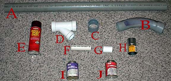
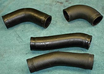
I have a new design for intercooler pipes that have really worked well for me. It's very simple and inexpensive and can be done in a couple of hours. If you do these modifications, do them at your own risk and responsibility. I am publishing this site to help people with their Mk3s because it is one of my hobbies and I just want to share what I have learned. All the parts are readily available at Home Depot or Lowes for less than $20.00. You will need a few of the original silicone hoses off your car for the connections to the 3000 pipe and Intercooler. You will also need a piece of exhaust tubing from any parts store and you may want to pick up a couple of new clamps just so it will all be new!
TESTSMy tests could be a lot more accurately done with better instruments, and are really quite crude, but I have not seen any other efforts to test the stock system. These are just my estimations, and I suggest that you do your own and as I have stated, do these modifications at your own risk! **Any time you tamper with systems on the car that will change the temperatures of the exhaust gases, you are taking risks.** EGTs that are too high will cause severe engine damage. I have not damaged my car with EGTs that have never gone past 1450 F, but that is my car with my tuning. Yours may be different, plus to know for sure, you would need a wide band oxygen sensor (I recommend the AEM because of the price and the replacement sensor is less than $70.00), so be careful!
***I have ran a few tests on this system with one stock intercooler and the stock turbo. I used a VDO boost gauge and two SunPro temperature gauges. With my boost controller set to 15 psi at the intake manifold (it has it's own sensor to maintain the proper setting at the manifold) and the VDO tapped in approximately six inches before the intercooler in the PVC pipe, the boost measured 15 psi, just as it should. Then with the VDO tapped in approximately six inches after the intercooler in the PVC, the boost pressure was measured again with the same results, 15 psi indicating no measurable pressure drop from the intercooler.
After this, I took the two temperature gauges and plumbed the sensor probes into the same holes that the pressure measurements were taken in (of course the holes had to be enlarged). With one gauge six inches before and one gauge six inches after the intercooler, the temperature readings were taken at highway runs in fifth gear. It should be noted that these readings were taken in fifth because there was not enough time in other gears to get a reading. On 15 psi runs and 68 degree ambient temperatures, the temperatures before the intercooler reached just under 295 degrees Fahrenheit. This is the section between the turbo and intercooler, and the hottest section in the system (and no, the PVC does not melt or deform)! At the other temperature sensor, after the intercooler, the readings peaked at slightly less than 150 degrees Fahrenheit. That is very good in my opinion, considering the heat that is put out of the stock turbo at 15 psi. I would estimate that the stock turbo is only about 60% efficient at 15 psi and would not recommend running this level of boost with the stock turbo on a regular basis. This test was simply to test the PVC/stock intercooler efficiency. I believe that the stock intercooler system is actually better than most people think. I believe that the pressure drop reported is due to the stock intercooler pipes, not the intercooler it's self.
You may also want to check Gus Mahon's (http://home.earthlink.net/~turbogus/index.html) site and see what his tests (http://home.earthlink.net/~turbogus2/intercoolers.html) reveal on the stock Mk3 intercooler as well as several others including the Spearco and Isuzu NPR.
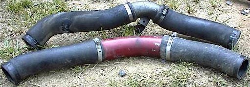
You can see in this picture of the lower section of the PVC pipes, the turbo to intercooler section which is the hottest, that after about a years worth of use and regular hard driving (I have a VERY heavy foot!) that the PVC has not deformed or melted in any way. If there is a weak spot in the system, I guess that would have to be it, but I have not experienced any damage or downtime at all in the 2.5 years I have been running this setup.
