Ever get tired of having to fool with those little jumper wires in the diagnostic block to check error codes and adjust your timing? I did so I decided to put a switch in the cockpit of the car that would connect E1 and Te1 when flipped. I put the switch in the place where, on older models, the head light washers would have been. Now all I have to do to adjust the timing or check diagnostic error codes is to flip a switch. When all done, flip the switch back over to return to normal. In this location, it is out of the way and very unlikely to ever be accidentally bumped or thrown. This is one of the best things I have done. I am always checking the ignition timing as well as for error codes. It just makes it easier to keep a close eye on everything.
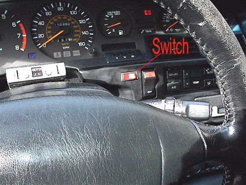
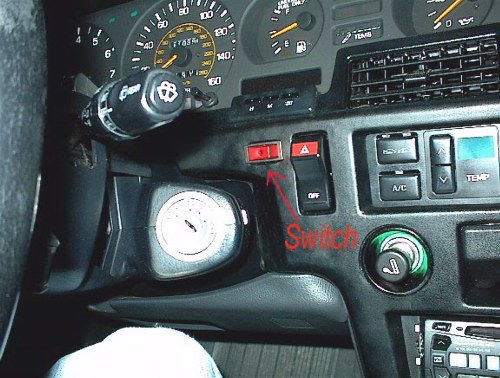
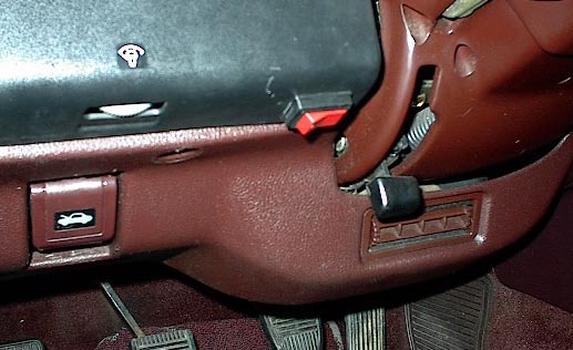
Alternate placing for the switch. This is how I have it on the 87.
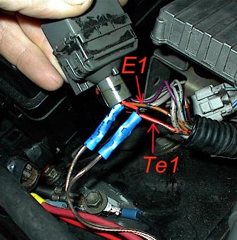
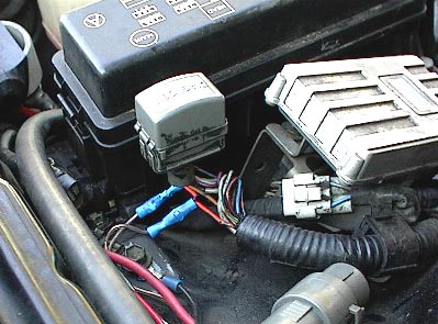
All you have to do is to tap two wires into the Te1 (red with green stripe and black dots) and E1 (Solid brown with black dots) wires of the diagnostic block on the under side and then run them through the fire wall to the switch. I did not cut these wires, I simply stripped a section of the insulation off and bent the wires so that they will fit up into the crimps as in the diagram.

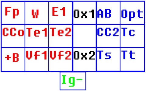
This is the diagnostic block labels on 89-92 models. This is what they are from the front of the car, engine is on the left and drivers fender on the right. The Ig is separate and covered with a small rubber cap. The terminals Fp and +B are the ones connected to bypass the fuel pump relay resistor (see section under the trouble code chart for more information). Te1 and E1 are the ones connected to check and adjust timing and extracting ECU error codes. E1 and TS (TEM on 87-88 models) are the ones switched for the TEMS mod.

The actual amount of the fuel mixture adjustment correction made by the TCCS's long and short fuel trims can be determined by using the Vf data output. The prime function of the Vf voltage data is to display what the condition of long and short fuel trim levels is.
The Vf data line emits 5 stepped voltages in the range of 0, 1.25, 2.5, 3.75, 5.00 volts. The TCCS will always output one of the five voltages to the Vf terminal in the diagnostics connector under the hood. The voltage is measured at anytime between the E1 and Vf pins in the diagnostics connector when E1 and T1 are not shorted. Remember that the voltages are stepped in 5 levels as mentioned above! Depending on your car you may see 3.5 volts rather than 3.75 volts, this is normal and you can ignore the difference in the voltages. The following is an example of the Vf voltage reading compared to the fuel correction required to make the fuel mixture correct:
[0 volts] Maximum Lean, reduction of the fuel mixture from the BASIC FUEL CALCULATION
[1.25 volts] Minimum Lean, reduction of the fuel mixture from the BASIC FUEL CALCULATION
[2.5 volts] No correction at all to BASIC FUEL CALCULATION
[3.75 volts] Minimum Rich, increasing the fuel mixture above the BASIC FUEL CALCULATION
[5 volts] Maximum Rich, increasing the fuel mixture above the initial calculation NOTE: THE TCCS IS ALWAYS MAKING THE AIR/FUEL MIXTURE CORRECT FOR YOUR ENGINE. THEREFORE THE Vf VOLTAGE INDICATION SHOWS YOU HOW HARD THE TCCS IS WORKING TO MAKE THE AIR/FUEL MIXTURE CORRECT. Remember that {0 volts Maximum Lean} does not say that the car is running lean! It is saying is that the TCCS is leaning the BASIC FUEL CALCULATION to make the mixture perfect for the current conditions. There was too much fuel calculated for the BASIC FUEL CALCULATION causing the engine to run RICH for a short time so the TCCS is reducing the fuel amount from BASIC FUEL CALCULATION. The 0 voltage LEAN is a very safe or normal reading, it is telling you that there is plenty of room to add fuel, lots of correction reserve left. Many stock cars running at high altitude will show a 0 volt condition, high altitude is less air for the engine, so the TCCS cuts back some of the fuel to compensate for the to rich mixture.
Back to Top
For God so loved the world, that he gave his only begotten Son, that whosoever believeth in him should not perish, but have everlasting life.
John 3:16
This site was built and is maintained by John B. Lunsford.
If you experience any difficulties or have any site specific questions or comments, please email me at Webmaster.
Please direct all other email to John@JBLMk3.com.


