I found this in the Supras archives. I had to hook up all the wires and tape them to my fingers because you have to touch two of them together at the same time you separate the other two. My friend at the local Toyota dealership said that they have a device that they just plug into the diagnostic port and hit a button and in about 10 seconds it's clear. So, if you can't get it to clear, they probably won't charge you anything to do something that simple.
(TSRM) ABS Diag. Code 41 - Malfunction Stored in memory If a malfunction occurs in the airbag system, malfunction codes 11 to 31 may be output, and when the battery is disconnected after the malfunction is repaired, malfunction codes 11 to 31 will be cleared, but code 41 will be output instead. So long as the cancellation operation for a malfunction stored in memory (see page AB-31) is not performed, code 41 is stored in the center airbag sensor assembly and the airbag warning light remains lit up. (AB-31) Clearing of diagnostic code 1. Clearing of malfunction code (except code 41) Remove battery negative terminal or ECU-B fuse for 10 seconds or more with the ignition switch OFF. NOTICE: When connecting the battery after canceling the malfunction code, always do it with the ignition switch in the LOCK position. If the battery is connected with the ignition switch in ACC or ON position, there are cases when the diagnosis system does not operate normally. HINT: Code 41 cannot be cleared by this method. The lower the temperature, the longer the battery negative terminal must be left off. Other memory systems (clock, audio system) will also be canceled out (See page AB-2) 2. Clearing of malfunction code 41 stored in memory. a. Connect the service wires to terminals Tc and AB of the check connector (diagnostic block under hood) b. Turn the ignition switch ACC or ON and wait approx. 6 seconds c. Starting with the Tc terminal, apply body ground alternately to terminal Tc and terminal AB twice each in cycles of 1.0 +/- 0.5 seconds. Finally, keep applying body ground to terminal Tc. HINT: When alternating between body ground of terminals Tc and AB, simultaneously release one from body ground while applying it (body ground) to the other terminal. If the time interval in between is too long, code 41 will not be cleared. d. After several seconds, when the airbag warning light starts to blink on a 64 m second cycle, cancellation is complete.
HINT: This method clears not only code 41, but also other malfunction codes all at once. Except when instructed by the troubleshooting procedure, use this method only when the repair procedure is completed.
**Valve Clearance Adjustment**
Some help pictures have been added at the bottom of this page.
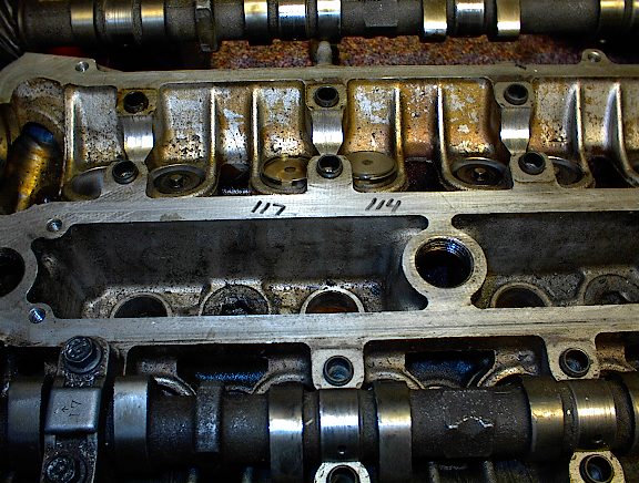
After the rebuild my car was making an excessive clicking sound so the valves were the first thing I suspected. Once I measured the clearance of the valves on the head, I found that all the intake valves needed adjustments of ten to twelve-thousandths. You can measure your valve clearances by removing the valve covers exposing the cams. You must loosen and lay aside the timing belt. I positioned the timing marks to top dead center and marked where the teeth were on the timing gears and on the belt. Going from the first lobes of the intake cam, point the lobes away from the shim and using feeler gauges, measure the clearance between the back of the lobe to the shim (the shim sits on top of the cap on the valve springs) see picture below. Repeat this for each of the lobes of both cams. On the intake side, there should be six to ten-thousandths clearance. On the exhaust side, there should be eight to twelve-thousandths (intake is average of eight-thousandths, exhaust is average of ten-thousandths) . If the clearance is less than the specified amount, then you must install a shim that is thinner than the one present. If it is more than the specified amount, then you must install a thicker shim. The shims you will need to purchase are the smallest of the three sizes Toyota makes. Shims can be purchased from your local Toyota dealership but beware, they are pretty expensive at around $7.00 each here in Asheville, NC. I'm sure you can get them cheaper if you look around. Measure all of the valve clearances and carefully mark them on a piece of paper so that you wont get them confused. Once this is done and you are sure of your measurements, reposition the cams to top dead center and remove them. Take out each shim one at a time and mark where it came from and measure the thickness of each with calipers and mark the measurement along with the clearance of that specific valve (see pictures). If the clearance of the valve is more than the specified amount, take the average clearance and subtract if from the measured clearance and then add that amount to the thickness of the existing shim. This will give you the thickness of the shim you need to bring the clearance back into specs. If the clearance is less than the specified amount, then take the measured difference and subtract if from the specified average and then take the difference away from the thickness of the existing shim. This will give you the thickness of the shim you will need.
--------------------------------------
EXAMPLE, valve clearance is excessive:
--------------------------------------
The measured difference of exhaust valve number one is fifteen-thousandths.
The shim thickness is 110 thousandths.
The specified clearance should be eight to twelve-thousandths with an average of ten-thousandths.
You would do the following:
MEASURED DIFFERENCE less SPECIFIED AVERAGE
or
fifteen - ten = five.
Then take your answer (five) plus INSTALLED SHIM THICKNESS
or
five + 110 = THICKNESS OF SHIM NEEDED.
So you would need to install a new shim that is 115 thousandths thick to bring the valve clearance back into specs.
--------------------------------------
EXAMPLE, valve clearance is too little:
--------------------------------------
The measured difference of exhaust valve number one is four-thousandths.
The shim thickness is 110 thousandths.
The specified clearance should be eight to twelve-thousandths with an average of ten-thousandths.
You would do the following:
SPECIFIED AVERAGE less MEASURED DIFFERENCE
or
ten - four = six.
Then INSTALLED SHIM THICKNESS less your answer from above (six).
or
110 - six = THICKNESS OF SHIM NEEDED.
So you would need to install a new shim that is 104 thousandths thick to bring the valve clearance back into specs.
Once all the shims are back in place and the cams are back in place and torqued to the proper setting, turn the cams by hand around several time to make sure that they turn freely. Then measure all the clearances again to make sure your measurements are correct.
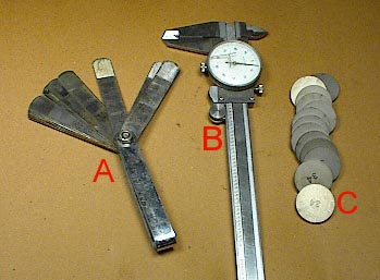
You will need: A. feeler gauge set, B. calipers, C. replacement shims in addition to the usual tools.
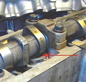
You must make sure the cam lobe is pointing away from the shim. It is the space between the backside of the lobe and the shim underneath that is called the "clearance" and is what you measure and adjust.
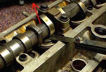
Measure the clearance with the feeler gauge. When the correct size feeler gauge is inserted, it should just slide between with a slight amount of resistance. You should not have to force the feeler blade in but it should not go in without any resistance at all either. Measure all the valve clearances and double check your measurements before you take the cam out. If you do it right and measure correctly, you should only have to take the cam out once.
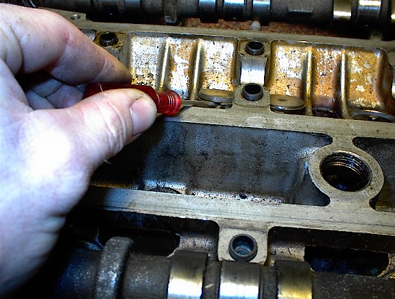
Flipping the shims out with a small screw driver.
You can mark each shim size on the head right beside where it came out so you don't get confused or forget. Make sure you put an adequate amount of oil on the cams and the head/caps before you reassemble. You should also use a quality assembly lube on the bolts. Make sure you don't over torque the bolts.
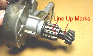
Cam Position Sensor (CPS) Alignment
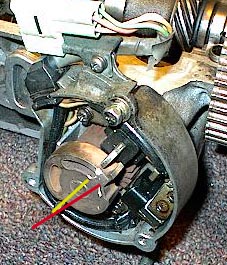
This is how the book says the alignment should be. Line up the hole on the shaft to the dash like mark on the gear.
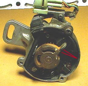
With the marks in the top picture are aligned, the "pole piece" should point to the G1 pickup, as indicated by the red lines.
Here, I have found that when I align mine like this, it winds up being out so that the cam has to be adjusted all the way to one extreme for the car to even run. This leaves no room for adjustment. I would guess that this is due to several different things, like the head and block being shaved, etc. I align mine like the pictures below and it always turns out perfect.
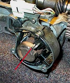
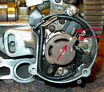
Just as the cps gears begin to touch the cam gears, this is how the "pole piece" and the G1 pickup line up with each other.
After the CPS is fully inserted against the head, the "pole piece" and the G1 pickup are not aligned perfectly. The "pole piece" is just a little past the G1 pickup in the clock wise direction.
Here is a better picture of the correct CPS alignment.
Depending on the head gasket thickness and amounts taken off the head and block deck (if you've ever had it done) which shortens the distance between the cam pulleys and the crank pulley, the amount of difference in the line up may vary slightly. In my experience, every single Supra I've ever worked on winds up aligning just like the picture directly above with the "pole piece" (center piece) pointing just clockwise past the G1 pickup.
For God so loved the world, that he gave his only begotten Son, that whosoever believeth in him should not perish, but have everlasting life.
John 3:16
This site was built and is maintained by John B. Lunsford.
If you experience any difficulties or have any site specific questions or comments, please email me at Webmaster.
Please direct all other email to John@JBLMk3.com.