Rear Suspension
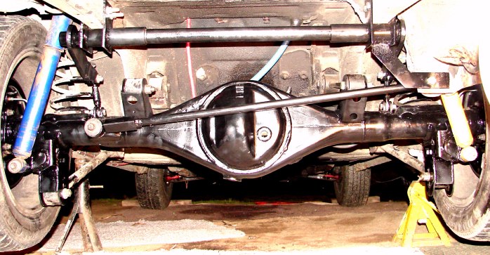
Above you can see the 4 cyl. 8" (G code) axle housing and differential (changed, see below) and the suspension system of my car. I have not modified the control arms yet, but I plan on making them adjustable sometime in the future (done, see below). I have shortened the panhard rod to center the the unit.
Anti-Roll Bar
An anti-roll bar is used to keep the rear suspension travel between the body and the axle housing the same on both sides. This keeps weight transfer even on both tires and helps the car to track straight when spinning and equalize weight transfer and traction to both tires. Without it, the rear right of the car will squat down while the rear left rises up and at the same time the drive shaft tends to push the left wheel down and the right one up. This causes the right tire to unload causing the car to go to the right suddenly (with slicks). It is not nearly as noticeable with street tires. The anti-roll bar is the remedy for this.
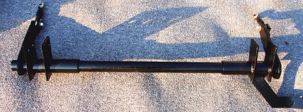
Here you can see the home made anti-roll bar I made. It is two pieces of pipe, one fitting into the other with a bushing (not visable) made of PVC (sink trap).
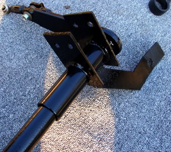
The bar is mounted to the frame with these two mounting plates on each side.
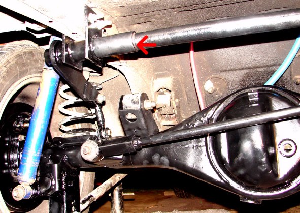
The PVC bushing is here (red arrow) between the to pipes to make a cushion and eliminate play.
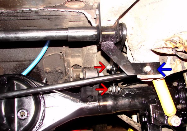
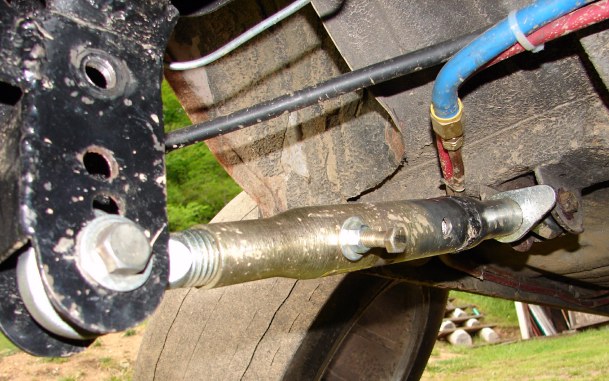
The red arrows indicate the 3/8" rod ends (7100 lbs. static load rated) that connect the anti-roll bar arms to the axle (one on each end). The blue arrow is a support bracket from the anti-roll bar to the mounting location on the frame for the panhard rod. This is to reinforce that area because some of the surrouding material had to be removed to make room for the arm of the anti-roll bar to move up and down.
![Anti-Roll bar link]](celica_graphics/sus_diff/arb3.jpg)
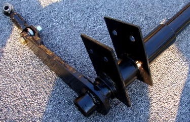
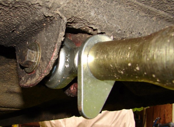
Here's a look at one of the links. It's made of a very short section of chrome moly tube with a nut welded in each end for the adjustable rod end to thread into, along with a lock nut. Two tabs are welded onto the axle housing to connect the link to.
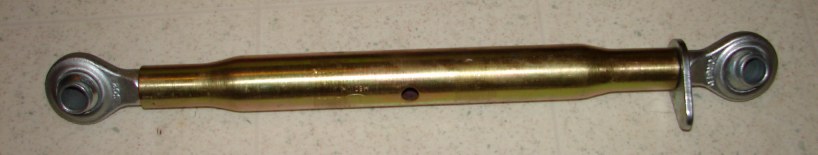
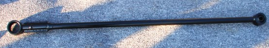
Adjustable lower control arm made from a top link for tractors from Tractor Supply. The part number is 0267759 and it cost $18.64. Pretty cheap for an adjustable control arm! I did have to shorten it, though. I had to take 3" out of the body.
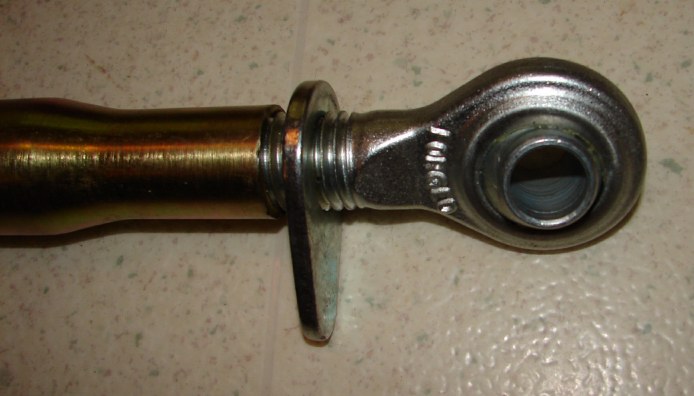
The rod ends have 3/4" threads and the 'eye' is 3/4" ID so that the piece from the center of the stock control arm will fit right in. It's just a tiny bit shorter, which gives just the perfect amount so that you can weld them so there is no play. These are very heavy duty units at 7 lbs. each. This makes adjustments very quick and easy and now there is no need for aftermarket bushings (if there are any).
These arms only have a lock on one end. You tap it with a hammer to secure it. I drilled and tapped a hole into the tube and put a bolt and lock nut to secure the other end for now until I can find a left thread 3/4" nut to use as a lock nut.
Notice the control arm's extended mounting bracket on the axle housing. The lower the mount the better. As you accelerate, the axle housing tries to turn opposite of the wheel. This pushes the lower control arms forward and the lower mounting point increases the 'lift' effect on the frame as well as the tire planting effect. The very top hole (almost clipped out of the picture) is the original mounting point.
Back to Top
For God so loved the world, that he gave his only begotten Son, that whosoever believeth in him should not perish, but have everlasting life.
John 3:16
This site was built and is maintained by John B. Lunsford.
If you experience any difficulties or have any site specific questions or comments, please email me at Webmaster.
Please direct all other email to John@JBLMk3.com.


